Pro / Installation approach
Understand the parts. Plan the installation.
The new commercial designs are being engineered for their first complete prototypes. The earlier bench generation below provides an assembly reference; its enclosure and purchased display are different from the new product design. Follow the instructions for the exact hardware revision in hand.
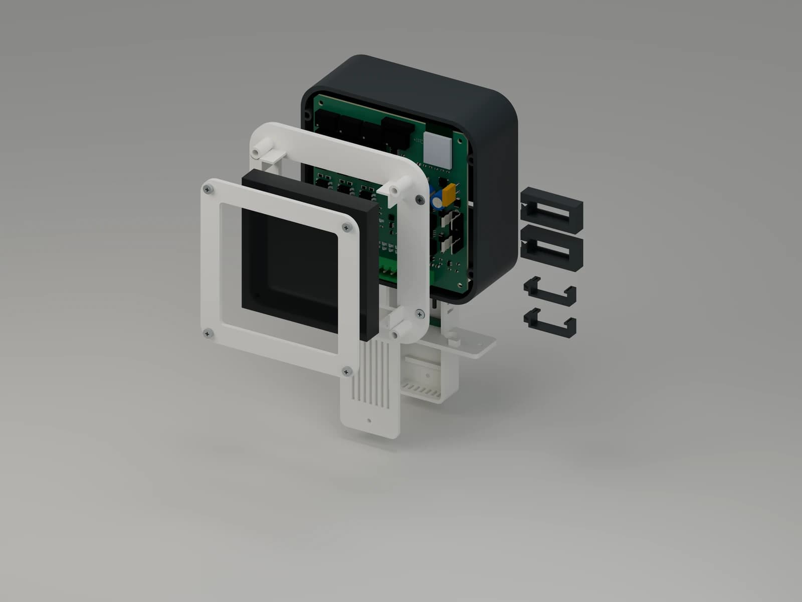
From design to evaluation
Three steps, in the right order.
- 01
Review the equipment
Identify the transformer, call wiring, existing safety devices and sensor locations. Select a suitable protected test arrangement and confirm compatibility before connecting a prototype.
- 02
Assemble with access in mind
Ease uses a screw-assembled backbox, display bezel and terminal cover. Signal uses a separate housing near the equipment, with air probes and a current transformer installed in their specified locations.
- 03
Prove the first article on the bench
Use the supplied build instructions to inspect polarity and wiring, test power rails with dummy loads and check fault behavior. Physical qualification precedes any decision to evaluate on installed equipment.
Earlier bench generation
Match the instructions to the hardware.
These figures describe the bench design reviewed on September 4, 2026. Final dimensions for the new commercial Ease will follow completed component fit and power checks.
- Earlier bench enclosure
- 122 × 125 × 69 mm overall, excluding the separate wired sensor pod. These are not the new commercial enclosure dimensions.
- Earlier bench display
- Waveshare ESP32-S3-Touch-LCD-4B. Four-inch, 480 × 480 pixels; nominal module 86.5 × 86.5 × 14 mm. The new commercial design uses a different display assembly.
- Control architecture
- Seven relay channels on the base; a separate processor and purchased touchscreen for the interface.
- Signal sensing
- Protected, externally energized 24 VAC call inputs, two air-temperature probes and one current-transformer input. No switching outputs.
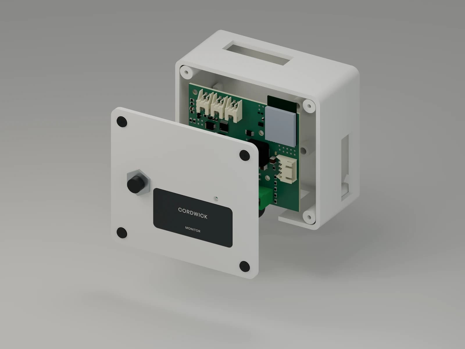
Power, isolation and first-article checks
Follow the revision-matched build instructions. The thermostat’s rectified DC ground is not transformer C. The protected bench procedure addresses programmer and instrument isolation before power is applied.
Ease rails are tested with dummy loads before the purchased display is connected. Call loads, transformer capacity and simultaneous loading must remain within the documented prototype limits. Fuse ratings do not establish instantaneous current limits.
Any field evaluation requires completed physical checks and a qualified installer’s equipment review.
Start a conversation
Bring your experience to the next step.
Tell us about your equipment, your service work and what you would want to learn from a prototype evaluation.